Introduction
The first draft of this post had a bit of a long introduction.

So, let’s try and keep it short and sweet. Here’s the gist of things. I want to design an Altair 8800 clone. By this, I mean a front panel computer controlled by toggle switches. I will do all design steps and verification in software first before building a prototype with actual hardware.
For clarity, let’s first talk about what this is not about:
- This is no introduction to digital design or any related matters. You should have some basic knowledge of digital logic and systems. If you know what a latch is and how tri-state logic works, you will be fine.
- This will not explain how a computer works or how to design one. You should know what a CPU is and how it relates to RAM, ROM, I/O, etc.
- This is no introduction to VHDL. You should have some basic understanding of VHDL. But if you’re experienced in some procedural programming language like C/C++, you should be able to understand enough of the code to follow (but be warned, VHDL is not programming).
- Neither will I explain how to get your code to run on an FPGA. This project will not use an FPGA. Unfortunately, there is a general misconception out there that VHDL and Verilog are programming languages for FPGAs. Both statements are wrong. Neither are they programming languages (this you will hear me say over and over and over again: VHDL is not programming), nor are they developed for use with FPGAs. Both HDLs predate the first FPGA. You can run code of any language on any FPGA provided the manufacturer (or someone else) provides synthesis tools for that language. You can synthesize Java code to run on an FPGA if you feel like it (you still shouldn’t do that). Hell, even Python.
But enough with the ranting and condescending elitism (most of the original 2000-words introduction was me ranting on the last point).
Now, what do I want to do differently? Instead of doing the prototyping and debugging on breadboards I want to use VDHL simulations to verify my design. VHDL or VHSIC Hardware Description Language is a (gasp) hardware description language (VHSIC stands for Very High Speed Integrated Circuit - does this qualify as a recursive backronym?). Basically, you can describe digital or mixed-signal systems with it and simulate their behavior.
Why VHDL? It includes all the tools I need to prototype my design. I can simulate any digital system’s behavior in software. And more importantly, it eliminates the need for expensive tools like an oscilloscope and/or logic probe to verify my design.
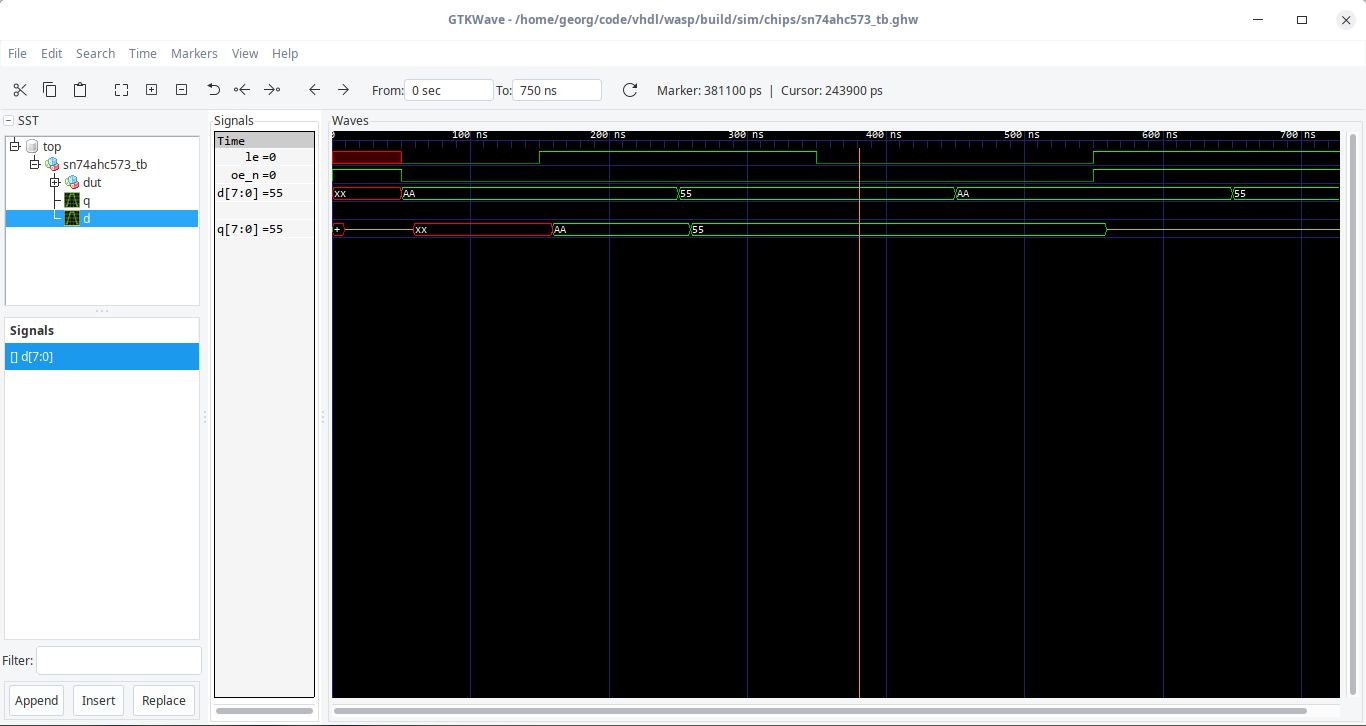
VHDL simulations can generate accurate timing diagrams (provided, of course, your code does reflect the simulated chips/systems behavior correctly). Here’s, for example, a series of signals applied to a SN74HC573 Transparent Octal D Latch and its response:

You can see the two control signals of the SN74HC573, LE (Latch Enable) and OE (Output Enable; the suffix _n denotes active-low signals). As you can see, the output pins q will correctly follow the values at the input pins d depending on the state of the control signals LE and OE. It will even show when q goes into high-impedance. If you watch closely, you’ll see that the simulation correctly accounts for propagation delay between input and output.
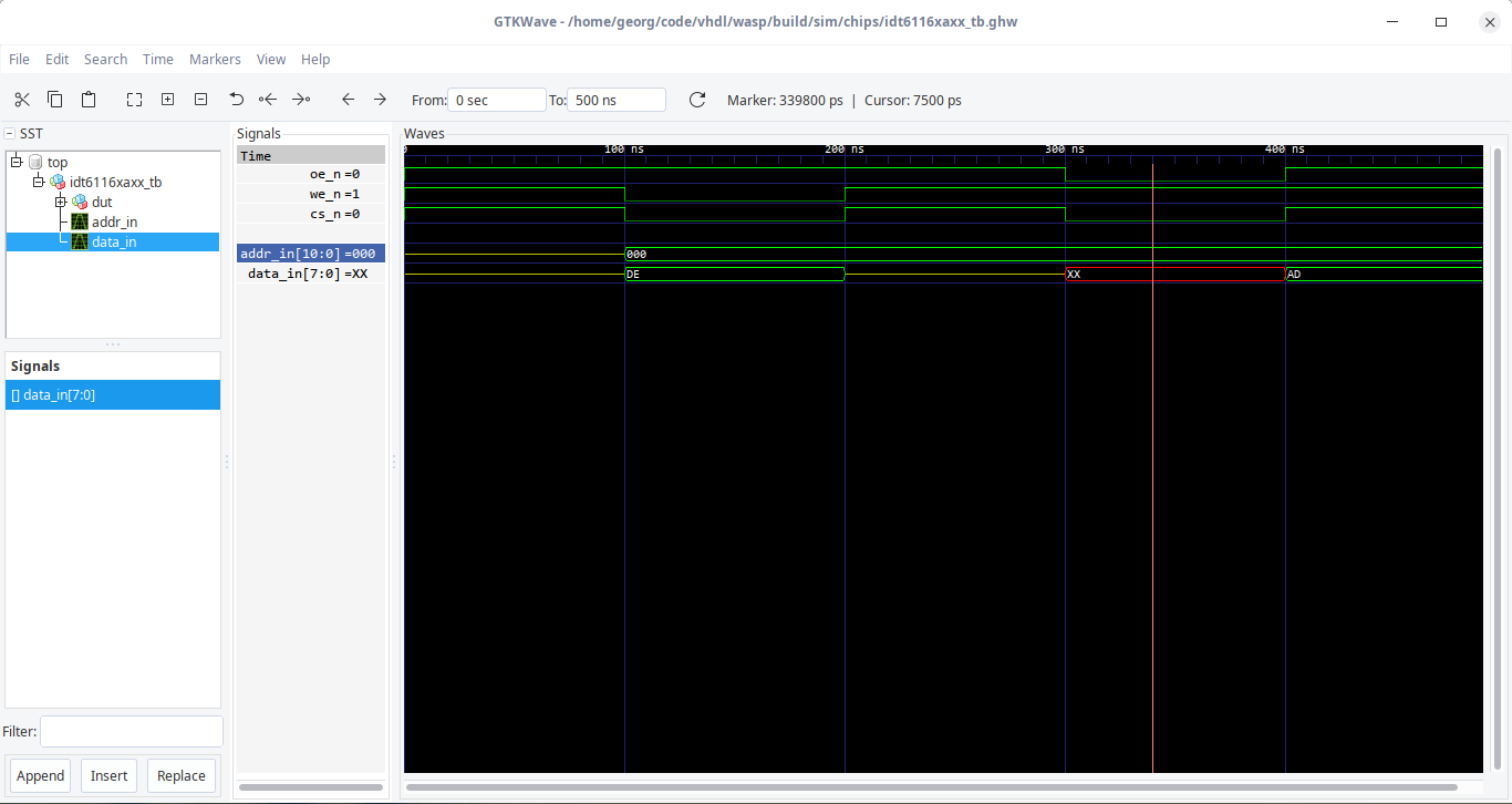
Now, the beauty of this is, I can even detect timing/signal conflicts this way. For example, here’s a diagram of the IDT6116SA RAM chip I plan to use in the Wasp (I’m calling my design Wasp, in case that wasn’t clear yet).

In this case, you can see a bus conflict between the 300 ns and 400 ns markings. The control signals of the chip indicate that we want to read from the chip while at the same time some external chip (say, an input buffer) is also driving the data bus - hence the data on the data bus is denoted as XX (or unknown) since the state (of one or more data lines) is ambiguous (e.g., the RAM chip wants to but data pin 0 D0 into a low state, will the input buffer wants it in high state; that’s bad and should not happen in a real machine).
This is only a small window into what I want to use VHDL for in this project. It will help me find and prevent a lot of errors and bugs in my design. Anyone who has done hardware debugging knows how tedious and frustrating it can be. I hope VHDL will help me keep my design robust enough so once I actually move to hardware, most of the bugs will already squashed.
Let’s talk about the Wasp itself to finish things off.
Basic Design of the Wasp
“Why Wasp?”, you might ask. Because I’m horrible at naming things.
Here’s what I want the Wasp to do:
- Run on an 8-bit CPU
- ROMless design with 8 x 2K of static RAM
- Allow single stepping/cycling code
- Have a simple front panel control interface with toggle switches and LEDs to represent data and information
- The control signal generation will sync with the system clock and be (hypothetically) frequency independent
As a minimalist and purist, I want to keep the chip/gate count as low as possible. Therefore, there will be no fancy stuff like UART interfaces to memory, data mass storage, connections to other systems, etc.
The last point may sound weird. I haven’t decided on a CPU to use yet (most probably something like the 65C02 or 6809 since I’m most familiar with them). I want to keep the design as independent of a certain CPU (architecture) as possible; some would consider this futile or even stupid. That’s what the last point is about: I want the control signal generator to generate signals for accessing RAM, stopping and running the CPU, stepping through code/memory without having to mess with the CPU. This will (hopefully) make a lot for sense once you see the actual design and code.
Conclusion
The Wasp is a minimal clone of the Altair 8800 with no fancy stuff attached to it. Next time, I’ll design the basic circuitry to access the RAM chip (think the Examine switch on the Altair) and buffer its content and finally drives some LEDs to show it to the user.
Credits
Blog Title Picture: MITS Altair 8800 Front Panel.jpg by Cromemco, released under CC BY-SA 4.0